Refraction of Light by Water
When a light beam strikes a plane interface between two media having different optical properties part of it is reflected and part is transmitted. The transmitted beam is refracted, or bent away from the direction of the incident beam. To explain this phenomenon one must resort to the wave theory of light, wherein light is an electromagnetic disturbance consisting of mutually perpendicular oscillating electric and magnetic fields, both of which are perpendicular to the direction of propagation. The theory predicts that the incident, reflected, and refracted beams, as well as the normal to the interface, are all coplanar.
Consider a monochromatic light beam travelling in air with velocity v(a) towards a water surface as shown in the figure. The angle between the beam's direction of travel and the normal to the surface, i.e. the angle of incidence, is 'i'. Assume for simplicity that the electric field vectors of all waves in the beam are oscillating perpendicular to the plane of the figure and, furthermore, that they are all "in step". This means that perpendicular to its direction of propagation the beam consists of a "wave front" along which the electric field vectors all point in the same direction and have the same magnitude. Because the vectors all oscillate in phase the wave front will pulsate as it moves, changing smoothly between a maximum electric field in one direction (a "crest") and a maximum in the opposite direction (a "trough"). The parallel lines in the figure denote the positions of consecutive wave crests. The time it takes the wave front to change from a crest to a trough and back to a crest again is the wave's period (denoted by 'T'), the inverse of which is the wave frequency, and the shortest distance between successive crest positions is the wave length.
When a wave crest reaches the surface of the water the oscillating electric field induces forced oscillations of the bound electrons in the water molecules. The electrons move back and forth, normal to the plane of the figure, with the same frequency as the driving electric field, and in so doing are continuously accelerated and decelerated. One consequence of Maxwell's equations of electrodynamics is that a charge undergoing acceleration is a source of electromagnetic radiation. The oscillating charges therefore radiate secondary waves in all directions. Each secondary wave combines (interferes) with an incident wave in such a way that their sum is a wave with a "retarded phase". This means, in effect, that the crests of the resulting wave travel more slowly than those of the incident beam. The crest speed, or phase velocity, in water is less than in air: v(w) < v(a).
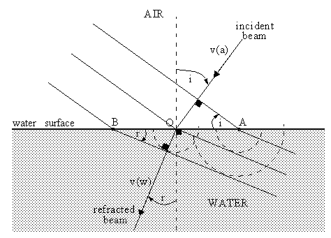
In which direction do the wavefronts travel in the water? In the figure, point A lies at the intersection of a line of incident wave crests and the surface of the water. It must also lie on a line of refracted wave crests. Otherwise, the electrons at A would be required to simultaneously perform two different kinds of oscillations, which, of course, they do not. Lines of crests must therefore be continuous at the surface of the water. Accordingly, as the wavefront in air advances by one wavelength v(a)T (speed times period) and the intersection point A moves to point O, the corresponding wavefront in water must also move one wavelength v(w)T in a manner that maintains a match of wave crests at points A and O, as shown.
The semi-circles in the figure are an interesting geometrical construction for deriving the direction of the refracted beam. About 200 years before Maxwell placed the wave theory of light on a firm mathematical foundation, the Dutch physicist Christiaan Huygens demonstrated that the laws of reflection and refraction could be deduced by assuming that each point of a light beam is a source of spherical waves travelling with the same speed as the beam. In our figure we show circles of radii v(w)T and 2v(w)T, corresponding to the loci of wave crests originating from the intersection points A and O. The tangent to the circles which passes through B is then a line of crests, and agrees with the continuity argument given above.
Referring to the figure, it is clear that
sin(i) = v(a)T / AO
sin(r) = v(w)T / BO
But AO=BO, so
sin(i)/v(a) = sin(r)/v(w)
Multiplying both sides by the speed of light in a vacuum, 'c', and defining the indices of refraction of air and water as n(a)=c/v(a) and n(w)=c/v(w) respectively, we get the final result
n(a)sin(i) = n(w)sin(r)
which is known as Snell's Law. Knowing the indices of refraction and the angle of incidence allows one to calculate the angle of refraction. The indices of refraction of air and water are approximately 1.00 and 1.33 respectively, so that
sin(r) = 0.75*sin(i)
indicating that when a light beam crosses from air into water it bends towards the normal to the surface.
REFERENCE:
R. P. Feynman, R. B. Leighton ., and M. Sands, "The Feynman Lectures on Physics" (Addison-Wesley 1963), Vol. 1, Chapter 31.